Gear Pump

What is a Gear Pump (or Viscous Fluid Pump)?
A gear pump, also known as a viscous fluid pump, controls the pump output using a set of gears to create a specific pressure and flow rate with low tolerance (usually less than one percent). Unlike peristaltic and diaphragm pumps, the pressure and flow rate fluctuation of the output fluid is low and negligible. Another important feature of this pump is the isolation of the fluid from any upstream flow variations.
The gear pump is considered the most common type of positive displacement pump and has a long history of industrial use. In 1593, a French man named Nicolas Grollier first drew a technical diagram of this pump. Later, in 1636, a German engineer named Papenheim invented the internal gear pump, which is still used for engine lubrication today.
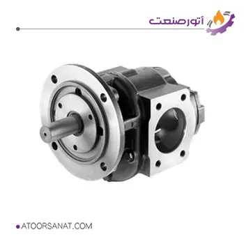
Features:
- Country of Origin: Iran
- Maximum Pressure: 5 to 6 bar
- Body Material: Cast iron
- Gear Material: Steel
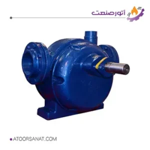
Features:
- Country of Origin: Iran
- Maximum Pressure: 5 bar
- Body Material: Cast iron
- Impeller Material: Steel
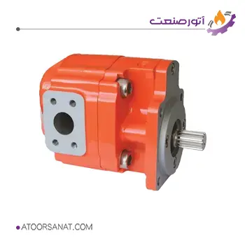
Features:
- Country of Origin: England
- Maximum Pressure: 25 bar
- Body Material: Steel
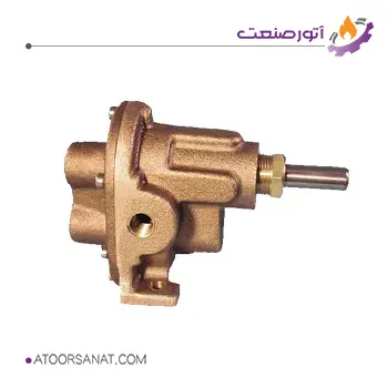
Features:
- Country of Origin: USA
- Maximum Head: 6 meters
- Applications: For transferring high-viscosity materials such as bitumen, heavy petroleum products, molasses, polymers, etc.
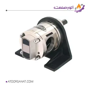
Features:
- Country of Origin: India
- Flow Rate Range: 8.3 to 300 liters per minute
- Applications: For transferring butter, oil, resin, chocolate, bitumen, solvents, paint, etc.
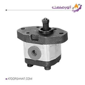
Features:
- Country of Origin: Iran
- Maximum Pressure: 250 to 275 bar
Gear Pump Operation
Various designs have been developed and manufactured for gear pumps. In this section, some of the most common designs will be examined.
- Gerotor Pump: The simplest type of gear pump is the gerotor pump. The following figure shows the general structure of the gears in this pump. In this pump, the number of teeth of the internal gear is one less than the number of teeth of the external gear. This difference causes the internal gear to rotate around the axis of rotation of the external gear. The geometry of the pump is such that in each half-turn of rotation on one side of the pump, the distance between the two gears increases, and on the other side, this distance decreases, and the opposite happens in the next half-turn. In the image, there are two kidney-shaped forms, where the left shape is the pump outlet and the right shape is the pump inlet.
As shown in the figure, with the increase in distance in the inlet section, a void is created and suction occurs. Due to the smaller number of teeth of the internal gear, its number of revolutions is also higher, and the fluid moves with it towards the outlet. In the outlet section, due to the decrease in distance, the fluid is forced out under pressure.
- Internal Gear Pump: This pump is very similar to the gerotor type. The only difference is the presence of a fixed moon-shaped part. In this pump, both gears rotate on a fixed axis. This pump transfers fluid in three stages. In the first stage, the fluid enters the pump by rotating the internal gear and creating suction. In the second stage, the fluid moves with the internal gear towards the outlet, and in the third stage, it is pressurized and exits the pump.
- External Gear Pump: This pump has two similar gears, one of which is usually the driver and the other is the idler. The stages of operation are exactly the same as the three stages of the internal gear pump according to the figure. In this type of pump, the fluid passes through the two sides of the gears, so it pumps more flow rate than internal and gerotor gear pumps.
Components of a Gear Pump:
Given the variety of gear pump designs, some of the designed components in pumps differ, but the overall structure and main components are the same in most pumps. In the following, we will examine these components.
- Driving gear: Connected to the main drive shaft.
- Idler gear: This gear is rotated by the driving gear.
- Housing: Both gears are located inside the housing.
- Pump inlet
- Pump outlet
- Main drive shaft: This shaft transfers power from an electric motor or internal combustion engine to the driving gear.
- Relief valve: This valve is located at the outlet and opens in case of excessive pressure to prevent damage to the pump.
The clearance between the gears and the housing is very low (between 0.005 and 0.007 inches) so even a sheet of paper can hardly pass through this gap. Adhering to this clearance is essential to ensure that the fluid does not return during pumping and to create the appropriate pressure.

