Booster Pump

What is a Booster Pump?
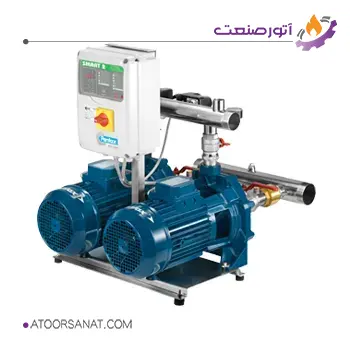
A booster pump is a complete pumping system designed to increase the pressure and flow rate of a fluid. Essentially, it comprises smaller subsystems such as pumps, control systems, and pressure tanks, forming a ready-to-use system.

Features:
- Country of Origin: Italy
- Maximum Head: 60 – 98.7 meters
- Body Material: Cast iron
- Impeller Material: Brass or Noryl

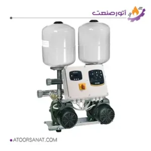
Features:
- Country of Origin: Italy
- Maximum Pressure: 6.4 – 6.5 bar
- Body Material: Stainless steel 304, cast iron
- Impeller Material: Technopolymer
How Does a Booster Pump Work?
In conventional water supply systems, the continuous circulation of clean water is a primary advantage. However, over time, various problems can arise within these systems. One of the most common issues is low water pressure, which can significantly impact both household and industrial applications. To resolve this problem, several solutions exist, and one of them is the use of a booster pump. A booster pump is a system consisting of one or more pumps designed to compensate for the shortcomings of simpler systems. It typically includes:
- One or more pumps that can have fixed or variable speeds
- Manifolds, valves, and expansion tanks
- Control gears, sensors, and communication systems
- This system is equipped with a controller and automatically maintains a constant fluid pressure.
The primary application of a booster pump is to increase the drinking water pressure in buildings or the main water network. However, these systems also find applications in various other areas such as agricultural irrigation, car washes, water treatment systems, industrial processes, and fire suppression systems.
In many countries, plumbing regulations limit the inlet flow rate of drinking water into buildings. For example, in some countries, the maximum allowable water inlet into a building is 12 liters per minute per unit. Additionally, in some agricultural irrigation wells, the pipe diameter is limited, and a high flow rate cannot be extracted.
Under such conditions, where the consumption flow rate exceeds the allowable inlet value, an atmospheric pressure tank is used so that the incoming water enters the tank before the pump. After the tank, water enters the pump, and under these conditions, a higher flow rate can be pumped to the destination with high pressure. Booster pumps usually have a standby pump to ensure continuous operation in case of any problems with other pumps.
Components of a Booster Pump System
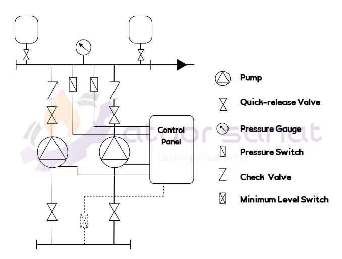
Booster pumps are typically complex systems composed of various components such as pumps, valves, sensors, and controllers. Each industrial manufacturer has its own unique design where all components are selected to work together to achieve a specific flow rate and pressure. The figure below shows a schematic of a booster pump system with two pumps, one of the simplest and most common systems.

The components of the above system are:
- Pumps:
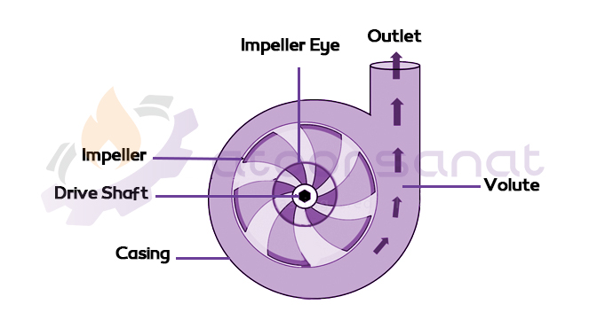
Most booster pumps use conventional centrifugal pumps. The reason for using these pumps is the low flow rate and high head required for most booster pump applications. A centrifugal pump consists of a stationary and a rotating part. As shown in the figure below, the fluid enters the pump perpendicular to the plane and through the eye.

- Pump Drives:
Pump drives are electric motors, which can be of various types depending on the existing conditions. If the system’s power consumption is low, ordinary two-phase electric motors are used, but if the power is high, the electric motors must be industrial and three-phase. The most important point about electric motors is compliance with the relevant standards.
- Ball Valve:
A ball valve is designed to safely stop or continue the flow of hazardous fluids or foreign gases. These valves are used to prevent the entry of compressed air in industrial processes or to isolate a section of the system from the circuit. The ball valve has many names that are used in different diagrams.
- Pressure Gauge:
A pressure gauge is installed in the fluid discharge line, and its main purpose is to visually check the system’s performance during periodic inspections. This pressure gauge is also often mechanical and has no connection to the control system and is only designed for the user.
- Pressure Switch:
The pressure switch is part of the control system that controls the operation of the pumps. This switch is usually set at two low and high values. Whenever the output pressure or the discharge line pressure is lower than the low value, the switch activates the system, and the pumps start working. The pumps continue to operate until the output pressure is higher than the high value set on the pressure switch. In this case, the switch turns off the system again.
- Check Valve:
The check valve only allows fluid to flow in one direction. Therefore, check valves are installed in the pump discharge line to prevent the fluid from returning to the pump.
- Pressure Tank:
If a pressure tank is not used in a booster pump system, for example, in household applications, each time a faucet is opened, the pumps start working, and for a very low flow rate of water, they are forced to pump the fluid again. Frequent on and off of the pump damages the internal parts of the pump such as seals, bearings, and impellers, and also significantly reduces efficiency.

