SET CONTROL

What is a Set Control (Digital Automatic Water Pump Switch)?
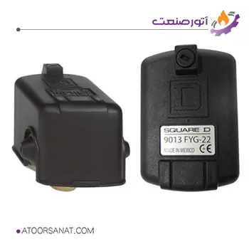
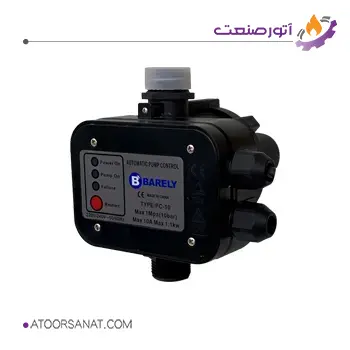
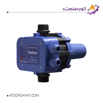
A set control, digital automatic switch, or pump controller is an electronic device that manages the operation of a pump. In fact, by turning the pump on and off at the right time, the set control maintains the flow rate and output pressure within a suitable range and optimizes the pump’s operation. Using it increases the pump’s lifespan and keeps the pump’s operating point close to its best operating point.

Features:

Features:
- Country of origin: China
- Maximum pressure: 10 bar
- Applications: for residential, agricultural, and other uses.

Features:
- Country of origin: China
- Maximum pressure: 10 bar
- Applications: for residential, agricultural, and other uses.
How Set Controls Work
A set control consists of electronic components for controlling the input power to the electric motor, sensors for protecting the pump, components for the proper operation of the controller, and other sensors for checking the operating conditions of the pump. Some of them are simple and are provided by the manufacturer along with the pump, but other set controls have more specialized functions and are designed for specific user applications. Because pump failure can cause many problems for the user, protecting the pump and electric motor is a priority in pumping systems. The minimum task to prevent pump failure is to ensure that the pump and electric motor do not overheat and that there is fluid in the pump when it is operating. A digital automatic switch can perform these tasks well.
The pump controller must know the status of the pump variables that are needed for protection and control. This means that the controller must be connected to a system that monitors the operating conditions. Pump performance monitoring includes:
- Electromotor overload: Protecting the pump when the electromotor current is higher than its rated current.
- Temperature sensors: Protecting the pump when the temperature of the pump and electromotor is higher than the permissible limit.
- Level sensors: Controlling and protecting the pump to ensure that the pump remains off if there is no fluid.
- Flow sensor: For checking the fluid movement.
- Pressure sensor: For adjusting the speed by the controller.
A set control can be designed to control one or more pumps. When talking about pump control, it means controlling the following:
- Turning the pump on and off based on information received from the following sensors:
- Level sensor
- Pressure sensor
- Flow sensor
- Controlling the pump using:
- Constant speed (low) – using a soft starter
- Constant speed (high) – using a solid-state starter to prevent water hammer
- Variable speed – using a variable frequency drive (pressure or flow control)
A digital automatic switch should be able to turn the pump on and off for the user, control the process, and monitor conditions based on the status of the alarms. Monitoring the performance of alarms includes:
- Main power: When the power connection is cut off.
- Pump control:
- Selecting the pump on and off status
- Selecting the manual off mode
- Setting the liquid level and pressure point
- Speed
- Monitoring:
- Pump operation light
- Alarm status light
- Liquid level and pressure
- Speed
Usually, in systems that use water, a set control has the following goals:
- Providing a minimum pressure of 30 psi in distribution lines
- Ensuring that there is a sufficient amount of fluid in the tank
- Protecting the pump and electrical equipment in emergency situations such as power outages, water cuts, voltage fluctuations, and faults in components and equipment
In the following, we will examine the operation of a system with a set control along with other common equipment. The bladder tank (shown as number 11 in the figure) contains compressed air and water, which are separated by a layer. As the water pressure changes, the volume of air also changes. If the water pressure drops below the permissible limit, the compressed air expands and activates the pressure switch, shown as number 4 in the figure. In this case, the controller activates the pump, and the water pressure increases. As the water pressure increases, the volume of air decreases, and when it reaches a certain limit, the pressure switch is turned off and the controller turns off the pump. By consuming water in the system, the pressure returns to the initial state of the process, and this cycle is repeated. By adjusting the pressure switch in the appropriate range, the number of times the pump turns on and off is reduced, and the water hammer is also prevented.
Types of Digital Automatic Switches
Digital automatic switches are used for both open-loop and closed-loop systems. In open-loop systems, the fluid passes through the pump only once and is consumed in other sections, but in closed-loop systems, the fluid is repeatedly transferred by the pump and acts as an intermediary for transferring energy or heat. The control method in these systems is different, and the most important difference is the controlled quantity, which is different in systems.
Components of a Digital Automatic Switch
The components of a set control include:
- Control housing
- Pressure sensing diaphragm
- Power input plug
- Connection assembly
- O-ring for sealing fluid inlet
- Output with support
- Electronic pressure control board

