Dosing Pump

What is a Dosing Pump?
A dosing pump, a type of positive displacement pump, is designed to inject chemicals or other fluids into a moving fluid stream. Often relatively small in size, dosing pumps provide highly accurate flow rates for maximum control of the output. These pumps are an essential component of dosing systems used to evenly distribute various fluids. The dosing process is utilized in a wide range of applications and industries, such as water treatment and food processing.
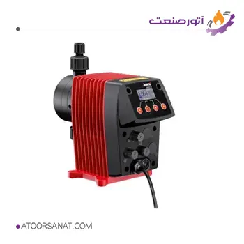
Features:
- Country of Origin: Germany
- Pressure Range: 1.5 to 400 bar
- Housing Material: PVDF, PP, PVC, Stainless Steel
- Pump Head Material: PVDF, PP, PVC, PE
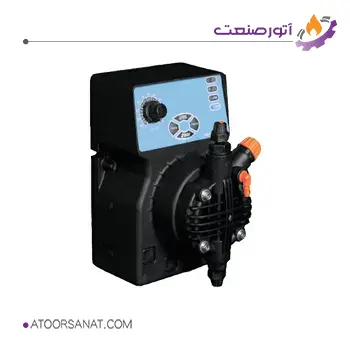
Features:
- Country of Origin: Italy
- Pressure Range: 1 to 95 bar
- Pump Head Material: PP, PVC, PVDF, AISI 316
- Tubing Material: Silicone or Santoprene
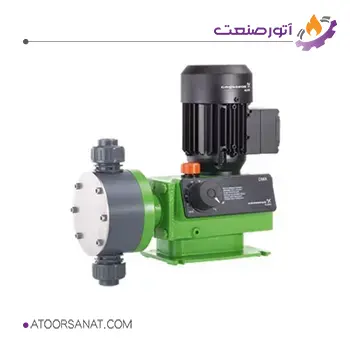
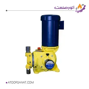
Features:
- Country of Origin: Denmark
- Maximum Pressure: 4 to 200 bar
- Pump Head Material: AISI, PVDF, PVC, PP
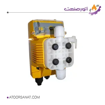
Features:
- Country of Origin: England
- Pressure: Up to 12 bar
- Housing Material: PP, Stainless Steel
- Pump Head Material: PP, Stainless Steel
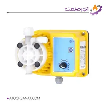
Features:
- Country of Origin: Italy
- Maximum Pressure: 0.1 to 20 bar
- Pump Head Material: PVDF, PP
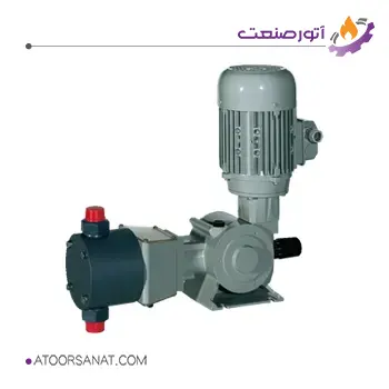
Features:
- Country of Origin: Turkey
- Pressure Range: 5 to 20 bar
- Pump Head Material: PVDF, PP
Features:
- Country of Origin: Italy
- Maximum Pressure: 10 bar
- Pump Head Material: PVC, Stainless Steel 316
- Impeller Material: Stainless Steel 304
How Dosing Pumps Work
The primary objective of all dosing pumps is to deliver accurate and controlled flow rates. However, there are various mechanisms to achieve this goal. In the following sections, we will explore some of the most common dosing pumps used in industry.
Diaphragm Dosing Pump
A diaphragm pump utilizes a piston, diaphragm, and inlet/outlet valves to fill and empty an internal chamber. The movement of the piston causes the chamber to fill and then inject a specific quantity of fluid into the process. While there are various models with differing diaphragm movement mechanisms, the general operating principle involves the piston pulling the diaphragm backward to create suction, drawing fluid into the chamber. As the piston and diaphragm move forward, the fluid is then pumped out.
The diaphragm serves as a barrier separating the fluid and the drive mechanism. The primary difference between a diaphragm pump and a solenoid pump lies in their drive mechanisms. In a diaphragm pump, the diaphragm is driven mechanically, whereas in a solenoid pump, it is driven by an electromagnetic coil. Let’s examine the operation of an air-driven diaphragm pump. While other drive mechanisms may have slight variations, the overall principle remains the same.
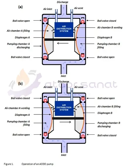
The image above shows a diaphragm pump with two diaphragms. Using two diaphragms ensures that while one side is drawing in fluid, the other is discharging it, resulting in a continuous fluid flow at the pump outlet. Consequently, these pumps offer smoother and more consistent operation compared to single-diaphragm pumps. The image above depicts a pneumatic diaphragm pump with two diaphragms connected by a central shaft. Air valves are located in the center of the pump.
In the first stage of the cycle, the air valve increases the air pressure behind the first diaphragm, pushing it towards the pump wall. This creates pressure in the fluid, causing it to be discharged, while the second diaphragm, which has been pulled backward, draws in fluid.
During suction, the air pressure behind the diaphragm equalizes with atmospheric pressure (the air vent opens), and the fluid, being at a higher pressure, lifts the inlet ball valve, allowing fluid to enter the chamber.
In the second stage, when the first diaphragm reaches its maximum displacement, the air vent of the second diaphragm closes, and compressed air from the source is directed to the back of the second diaphragm. This compressed air pushes the second diaphragm forward and pulls the first diaphragm backward.
At the second diaphragm, the outlet ball valve lifts due to the increased fluid pressure, allowing the fluid to exit. Upon completion of the second stage, the air reaches the back of the first diaphragm, and the cycle repeats.
Solenoid Dosing Pump:
A solenoid dosing pump consists of two primary components: the actuator and the fluid section. These components are connected via a connecting rod and a fluid diaphragm. The actuator utilizes an Electronic Pulse Unit (EPU) to energize the solenoid coil. The fluid section of this pump is similar to a diaphragm pump, with the primary difference being the actuator.
The EPU’s operating speed determines the frequency and stroke length of the diaphragm, which in turn dictates the fluid flow rate. Additionally, in many pumps, both the speed and chamber volume can be adjusted, allowing users to modify the output flow rate.
Ultimately, the user must adjust the stroke length and speed to achieve the desired flow rate. In some solenoid dosing pumps, the stroke length is fixed, and only the speed can be adjusted.
The reduction ratio is a measure of how much a pump’s flow rate can be reduced from its maximum value. This ratio depends on the number of strokes per cycle and the pump’s operating speed. Beyond these factors, solenoid pump actuators can offer additional features that enable precise and flawless chemical dosing processes.
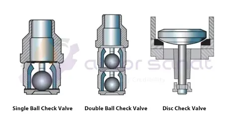
The fluid section comprises a diaphragm and one-way inlet and outlet valves. Due to their reliability and performance, ball valves are commonly used as one-way valves.
When the diaphragm is pulled outward, the outlet valve closes to prevent backflow. Simultaneously, the inlet valve opens, allowing fluid to be drawn into the chamber. Subsequently, the diaphragm is pushed inward, closing the inlet valve and opening the outlet valve, forcing the fluid out of the chamber.
While the operating principle of a solenoid dosing pump is relatively simple, certain features can be incorporated to enhance its reliability. These features include:
- Using two ball valves at both the inlet and outlet to ensure higher reliability and consistent fluid delivery in each pumping cycle.
- Incorporating combination filling ports to facilitate quick and easy filling of the pump with fluid.
- Employing materials that are chemically compatible with the fluid to prolong pump life.
Due to having only one moving part, solenoid dosing pumps typically operate without wear. These pumps require no lubrication for bearings or shafts, resulting in low maintenance and repair costs. Moreover, solenoid pumps excel in continuous operation applications.
Piston Dosing Pump
This type of dosing pump is designed to inject precise flow rates of chemicals into various processes, such as water treatment systems. In these applications, the water composition must be carefully analyzed, and the process must be precisely controlled. The operation of a piston dosing pump is analogous to injecting a needle into the body. As the piston retracts, fluid is drawn into the chamber.
Subsequently, when the piston is pushed forward, the fluid is discharged through the outlet. Therefore, in this pump, fluid is pumped by the reciprocating motion of a piston. A piston dosing pump typically consists of four main components:
Actuator: Generally, the actuator for this metering pump is a fixed-speed AC motor. However, these pumps can also utilize variable-speed motors and hydraulic, or pneumatic actuators.
Fluid-contacting section: The design and material of this section are determined by the fluid type and the intended application. Factors such as temperature, flow rate, fluid viscosity, and corrosiveness must be considered when selecting materials for this section.
Power transmission section: In this section, the rotary motion of the electric motor or any other actuator is converted into the reciprocating motion of the piston. In industrial pumps and high-flow pumps, this section is submerged in oil to ensure proper operation and reliability.
Flow rate adjuster: The flow rate of the pumped fluid is adjusted by changing the stroke length, effective cycle length, or reciprocating speed. As shown in the figure below, many piston dosing pumps use a precision screw for these adjustments. Alternatively, a pneumatic or electric actuator that responds to a signal can be used instead of a screw.
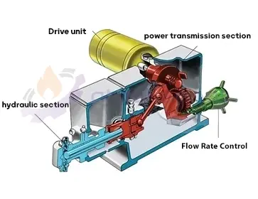
The reciprocating motion of the piston creates a flow that can be easily modeled as a sine wave. The flow rate is equal to the piston displacement per unit time. Additionally, unlike centrifugal pumps, the output flow rate of a piston dosing pump varies very little with changes in pressure. The flow rate versus pressure curve for a piston pump is linear, but if the cycle speed is halved, the flow rate is not necessarily halved. This is because the zero-point calibration may not pass through the origin of the flow rate versus cycle number graph. Although these pumps can produce flow rates from zero to maximum, their accuracy is only valid within a certain reduction range. Most dosing pumps have a reduction ratio of around 10:1, meaning the pump is accurate only within the 10% to 100% range of the nominal flow rate. Newer dosing pump models have reduction ratios of 100:1 and higher. All fluid sections in various dosing pumps share common characteristics. Initially, the fluid is drawn into the chamber by the backward movement of the piston and then expelled from the chamber by the forward movement. To facilitate this process, one-way valves are used at the inlet and outlet. During the suction process, the piston draws in fluid, lifting the inlet ball valve and allowing fluid to enter. Simultaneously, the backward movement of the piston and the resulting pressure keep the upper valve closed. The valve positions are reversed during the fluid discharge process. In addition to ball valves, other types of one-way valves can be used, as illustrated in the figure below.
